Building Layout | How to Building Layout | Construction Layout Techniques
Table of Contents
Building Layout
The true intention and intent of setting out (layout) are to move the plan, length, and width of the base on the ground so that the foundation can be excavated for the construction of the intended building according to the drawing.
Before actually preparing the construction of the building, the following preliminary works should be completed.
- Remove all grass, bushes, leaves, and other vegetation from the area.
- Make a note of the ground’s spot levels.
- Make a permanent bench mark in the development zone.
A building’s or structure’s layout depicts the plan of its base on the ground floor, as shown in its plans so that excavation can be carried out precisely as needed and the building’s location and orientation can be precisely defined. It is laid out in accordance with the engineer’s or architect’s foundation plan sketches and requirements.
To comprehend the architecture or setting out of a building, we must first comprehend some of the technical terms used in this field, which are listed below.
Baseline
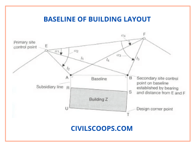
A baseline is a straight reference line that indicates where the building’s corners are on the field. It may be the outer border of a lane, a curb, the area’s boundary, or simply a line connecting two lines.
Horizontal Controls
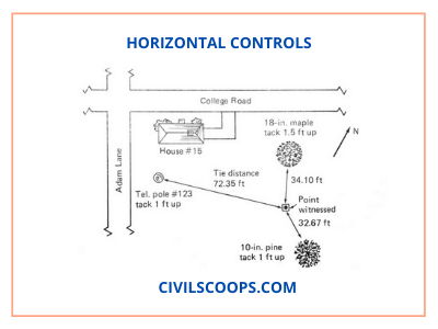
Horizontal controllers are points whose co-ordinates are defined in relation to a given location. These points are then used in a variety of ways to find other points on a layout, such as corners. There should be several control points to allow each point of the foundation design to be precisely placed on the earth.
Vertical controls
Vertical control points of known point compared to any given vertical datum are defined such that design points upon on work could be located at their correct levels. Vertical controls can be made out of 20mm diameter steel bolts that are 100mm long and forced into existing stairs, ledges, footpaths, and other structures with established reduce thresholds.
Batterboards and Offset Pegs
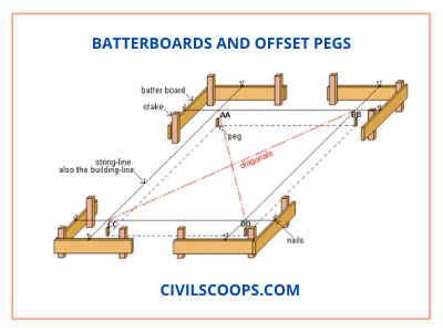
Once the pattern points are located on the earth, pegs are pushed into the ground at that location. The corner pegs will be lost once foundation excavations started. Offset pegs are used to eliminate these additional pegs. Batter boards are usually erected near each offset peg and used to reposition the points after the dig is completed.
How to Building Layout
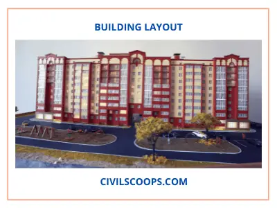
For a building’s demarcation, the protocol outlined below is advised.
- A baseline is marked on the ground for the layout of a house, either from the centre line of the road or from some permanent building nearby. This line aids in the identification of a building’s front. Side baselines may be identified with the aid of a side structure or lane, or with the help of the plot’s first baseline or boundary.
- Install temporary pegs along the centre line of the walls/columns on both the front and back sides of the walls/columns.
- Fix a peg in the middle of the walls/columns on both sides of the wall and columns on the opposite sides of the structure’s front.
- After you’ve fixed the pegs, examine the diagonal lines of the square or rectangle you’ve formed.
- Burji or marking pillars must be built with pegs at a range of 1.5 to 2 metres, with the top surface plastered.
- Label the centre line on the top of the Burjis with thread (Soot) or perhaps the Thedolite in large designs, and confirm the diagonal as well as other measurements.
- Burji is installed on all four corners of the house, and the top floor is set at a projected plinth level.
- With the support of the centerline drawn on the Burji, mark the base of walls/columns according to the drawing on the field.
- Chalk powder is used to label base trenches on the site.
- Excavate the foundations of the walls/columns to the desired degree, and verify the excavation with a centre line and level burji to prevent any complications later.
What Is Method of Layout of Building?
A line attached to corner posts marks the shape of a basic building layout, such as a rectangle. A nail in the top of the post may be used to connect the line to. To transform off 90-degree angles for the remaining corners, use a theodolite, site square, or builder’s square. To create a straight line between corner posts, ranging rods may be needed.
Corner posts are usually 50 x 50mm timber posts with a nail in the centre pushed squarely into the stone. Dry lime or a related powder may be used to draw the outline on the stone. At the corners, timber profile boards may be used. Profile boards are usually 0.6-1m tall and made up of two 50 x 50mm posts and a 150 x 38mm crossboard pushed at least 600mm into the deck.
Trenches
The scale, form, and orientation of the excavation, as well as the width and location of the walls, are all determined by trench configuration. After the building outline has been created, trenches are dug. For accurate hand excavation, the diameter is always indicated with a line of dots of dry lime powder, while the centre line is marked for accurate computer excavation.
Outline profile boards are often used to monitor trench distance, depth, and positioning. Profile boards should be placed at least 2 metres away from trench positions such that they do not impede construction activity. The profile crossboard’s level should be tied to the site datum and set at a suitable height above ground level, usually with cords strung between two profiles at either end of the trench. For identifying purposes, bands may be drawn on the crossboard.
Pegs are often pushed into the trench’s bottom to mark the top of the concrete strip that will be poured later.
With the aid of a spirit stage, the corners of walls are moved from intersecting cord lines to mortar
Spots on the Concrete Foundations.
Trenches must be cut with extreme caution, particularly if they are to be left open for a prolonged period of time, as the sides can cave in.
Reduced Level Excavations
Working from a baseline, the overall outline of a reduced level region can be established. Corner posts are secured to the excavation area’s outline, which is outlined with dry sand or similar material. Sight rails are placed at a suitable height and in places that enable a traveller to be used to monitor the depth of the excavation.
A traveller is a fixed-height profile board that is used to monitor excavated levels between profile boards. It is easy to see whether or not the excavation has been carried out to proper levels by having the traveller in the sightline between two level boards. The traveller’s height is equal to the sight rail’s desired level minus the excavated area’s formation level.
Framed Building
Framed structures are commonly based on a grid and are often measured from a baseline. Isolated or pad foundations have their centre points marked by the intersections of the grid lines.
A theodolite is used to map out the grid, and pegs are used to locate the grid intersections. Offset pegs or profiles should be fixed independent of the future excavation activity until the grid has been laid out. A traveller sighted between sight rails or a level and workers tied to a site datum may be used to monitor excavation depth.
Construction Layout Techniques
- To discern the proportions of the building plan, a string line is used.
- Corner stakes, batter boards, and posts are sunk with a sledgehammer.
- In certain soils, a posthole auger is used to dig the holes needed to properly set posts.
- The batter boards and posts are sliced with a handsaw.
- Sharpen batter-board posts and stakes with an axe or a hatchet.
- Building batter boards requires the use of a hammer.
- A chalk line is a tool for laying down chalk on a surface to create a straight guideline.
- A 100-foot/30-meter tape is used to measure diagonally (usually in 100-foot lengths) and to lay out drainage and base lines.
- For laying out excavation or base lines, tracing tape is used. The tape is about 1 inch thick and made of cotton fabric. It normally comes with a length of 200 feet.
- A carpenter’s level is used to sight level lines and level a floor. It can be used without a straightedge or directly on the board.
- A spirit bubble on a line level indicates that it is level. A taut line suspends the stage. When it is put halfway between the points to be levelled, it offers the best results.
- An automated level can determine grades over short distances by measuring estimated variations in elevation. In the tunnel, you can see the scenery, level bubble, and index line.
- String line is secured to batter boards with 8d nails.
- The corners of the house dimensions are located using a plumbing bob.
- A frame square is used to ensure that lines are square.
Control Lines Construction
The control line is the line that accounts for the extra margin; in most commercial and industrial areas, the size of the control line is one and a half times the width of the highway.
Construction Layout
Construction planning, also known as construction staking or site layout survey, is a method in which a builder reads the building plans (blueprints) and then marks the positions of all items on the construction site with stakes. These would include the house itself, as well as the septic system and well location.
[note note_color=”#F2F2F2 ” text_color=”#333333″ radius=”3″ class=”” id=””]
Like this post? Share it with your friends!
Suggested Read –
- How a Building Is Constructed | Components of Building
- What Is Bituminous Road? | Bituminous Road Construction | Bituminous Road Layers | Bituminous Macadam | Bituminous Road Construction Process | Advantages of Bitumen Road | Disadvantages of Bitumen Road | Application Road
- What Is Super Elevation? | Superelevation Definition | Purpose of Providing Superelevation in Roads | Calculation of Superelevation in Roads | Minimum and Maximum Superelevation in Roads | Method of Providing Superelevation to the Roads
- What Is Lintel? | Function of Lintel | Types of Lintel
- What Is Grouting | Type of Grouting | Experiment of Grouting | Characteristics of Grouting | Types of Grout for Ceramic Tile | Advantage of Grouting | Disadvantage of Grouting
[/note]
Originally posted 2021-08-04 07:48:23.

