What Is Tie Beam? | Tie Beam Details | Ties in Column | Tie Beam Design | Concrete Tie Beam | Tie Beam Reinforcement Details

Table of Contents
What Is Tie Beam?
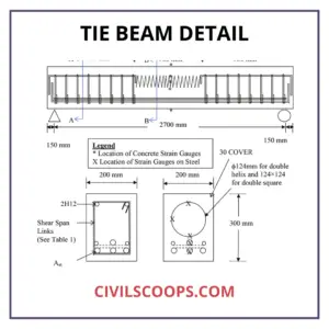
Tie beams are beams that link two or more columns or rafters in a roof or truss, or at some height above floor level, to strengthen and stabilize the whole structure at the base level, at the roof truss, and floor level, tie beams, and a plinth are usually supported.
They are unable to support any vertical loads, such as walls and other structures. Owing to the eccentricity of the vertical member (Columns) on the footing, tie beams may also behave as a bracing beam that carries all stresses. Tie beams are used as fixing members to reduce the supported length of a non-supported column.
Tie beams may also be used as a support for partition walls or other partition members. Tie beams may also be used as a tying factor to prevent settling between the strata and the footing.
Tie Beam Details

- These types of beams are used in buildings where the roof or slab height is greater than the structure’s normal height.
- In the columns, tie beams serve as a height breaker. The Tie Beam joins two or more columns together to maximize their effective length and slenderness ratio.
- Tie beams are length-breaking members that take no floor loads and serve as a length-breaking member for columns with a floor that is higher than the general height.
- Axial compression is carried by tie beams.
- The load of the rafter is transferred to the columns by tie beams.
- Tie beams keep heavily stressed slender longitudinal columns from buckling outward.
- Column footings or pile clips are linked by tie beams.
- As concrete is being poured, tie beams keep longitudinal bars in their original location.
- During seismic activities, tie beams hold the spread footings in their proper places.
- In the event of settlement, tie beams double as grade beams, redistributing vertical loads by moment and shear.
- Tie beams are used to reinforce inner or exterior walls strip footings.
- Over a pile base, tie beams act as grade beams to connect the pile caps and stabilize the superstructures.
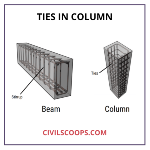
Ties in Column

- First and foremost, the rods must be straightened in order to make ties and preserve precise diameters. The rods used to make ties should not be less than 10mm in length.
- The rods should be cut and bent carefully based on the dimensions stated in the drawings; otherwise, waste would result.
- We must contact structural engineers and adhere to BNBC, ACI, and ASTM codes in order to ensure the proper specification and spacing of the connections.
For the connections to survive an earthquake, the following detailing must be maintained:-
- The hook of the tie should indeed be twisted at a 135° angle. The head portion of the ties must be widened by 10d. It ought to be 100mm, or 4 inches, for such a 10 mm rod.
- Earthquake resistance is also essential for the links in the member’s Centre section.
- We have to clean the primary rods thoroughly before inserting the ties into the column bars.
- Following that, the requisite number of ties should be given in the rods of the columns, based on the design and spacing of the ties. The ties’ hooks should be bent and positioned correctly at this time.
- After positioning the links, use the binding wire to secure them to the main rods of the columns (GI wire). The links must not be displaced from their original location after being fastened with cables.
- The links can also be installed in the joints of beams and columns for earthquake safety. In the joints of beams and columns, the proper number of connections should be given.
Tie Beam Design
The terms “tie beam,” “degree beam,” “earth beam,” and “plinth beam” are interchangeable. A tie beam is a beam that connects two columns to resist vertical and horizontal movement.
At every stage, tie beams can be mounted. They are known as plinth beams if they are installed at the plinth level, where they aid in the soil retention of the building’s inner area and also provide protection for the walls.
The tie beam’s design is determined by the volume of settlement of the base chosen for the project.
Concrete Tie Beam
The steel braced framed columns are supported by tie beams between columns on a Spread Footing. By constructing a tie beam to bear vertical and horizontal reactions from the frame, we must consider that it has a general concrete beam with an axial load. For axial compression-like axial column power, this axial load acts as a compression or tension load.
The steel area should also be thoroughly examined for the necessary axial stress. Since it is a stressed member rather than a compression member, the concrete’s sole purpose is to support the steel and bear the compression. Make sure you have delivered the necessary lap at the required splices after testing the Reinforcement.
The tie members may not need to be concreted over, but they must be secured. When it comes to Reinforcement, couplers are often preferred overlapped bars.
Tie Beam Reinforcement Details

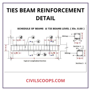
Tie beam reinforcement calculation is divided into two parts Main bars and stirrups.
Part – I: Main Bars
- In the top, right, and sidebars, measure the length of the main bars.
- Then look at how many main bars are in the top, right, and sidebars.
- Check the main bars’ diameter in the top, right, and sidebars.
- Calculate the overall length of the Main bars in both directions (top, right, and side).
- Calculate the average weight of the Main bars.
Part – II: Stirrups
- Measure the length of the stirrup by subtracting the concrete cover from both sides of the tie.
- Determine the length of the stirrup, including the hook.
- Determine the total number of stirrups.
- Calculate the average length of the stirrups.
- Determine the approximate weight of the stirrups.
- The structural engineer uses the load analysis to determine the length, diameter, and the number of bars.
Before you strengthen tie beams, keep the following points in mind.
- Position the Main Bars ( Top bar, bottom bar, and Sidebar ) from the centre of one footing to the centre of the next.
- Stirrups (rings) are given to connect one side of the footing to the other.
- Main bars should be given adequate development duration (top, bottom, and sidebars).
- Stirrups should have a minimum center-to-center spacing of 150 mm.
- Stirrups can be made after a sufficient cover, i.e., 25 mm, has been deducted.
- The Stirrups’ hooks need not be less than 10d in length (where d is the diameter of the bar).
- To avoid earthquakes, the stirrup hooks should be bent at 135 degrees.
Quantity of Reinforcement in Tie Beam
- Determine the tie beam’s overall length.
- Using the drawing as a guide, calculate the combined dead and live loads.
- Determine the optimum bending moment and shear force acting on the beam based on the load.
- The weight of 1 m of steel=d2/162 kg (where d is the diameter of the bar) and the amount of Reinforcement needed can be measured using this formula.
[note note_color=”#F2F2F2 ” text_color=”#333333″ radius=”3″ class=”” id=””]
Like this post? Share it with your friends!
Suggested Read –
- Types of Curing | Concrete Curing Time | How to Cure a New Concrete Slab | What Is Curing of Concrete | How Long Does Concrete Take to Dry | How Long Does It Take for Cement to Dry
- What Is Sheepsfoot Roller? | Characteristics of Sheepsfoot Rollers | Difference Between Padfoot and Sheepsfoot Rollers
- Monolithic Slab I Monolithic Definition I Monolithicfooting I Monolithic Slab Foundationl Monolithic Slab Foundation Design L What Is a Monolithic Slab L How to Form a Monolithic Slab
- What Is a Spillway | Types of Spillway | Definition Spillway | Spillway Design
- What Is Workability | What Is Workability of Concrete | Types of Workability of Concrete | Factors Affecting Workability of Concrete
[/note]
Originally posted 2021-09-27 10:14:14.
