All About of Shear Force and Bending Moment | What Is Shear Force | Shear Force Formula

Table of Contents
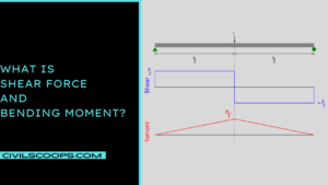
What Is Shear Force and Bending Moment?

Internal forces such as shear force and bending moment are representations of internal forces caused in a system when loads are applied to it.
Loading causes loss in two ways:
- shearing the beam around its cross-section and bending the beam.
- by bending the beam to an extreme degree
What Is Shear Force?
The shear force is defined as the force that acts perpendicular to just a surface and opposes an offset force that acts in the reverse direction. Shear strain is the consequence of this.
To put it another way, one section of the surface is moved in one way whilst others are moved in the reverse direction. Compression, is from the other hand, exists when 2 opposing forces propel together at the same time causing compressive stress.
If a structural member fails due to shear, two pieces of it are pulled in opposite directions, similar to how a sheet of paper is sliced with scissors.
Shear walls are used in large or high-rise buildings to provide resistance to shear forces that would otherwise drive parallel structural elements of a building over, causing racking.
Sign Convention for Shear Force
Here, the following methods of shear sing convention.
1. At a Part, the Shear Force Would Be Positive
- When the resulting of the forces to the left of the portion has been in an upwards position, the shear force at that section would be called positive.
- If a resulting of the forces to the right of the portion is in a downward motion, the shear force at that section would be called positive.
2. A Segment’s Shear Force Would Be Negative
- If a resulting of the forces to the left of the portion is in a downward motion, the shear force at that section would be called negative.
- Whereas if resulting of the forces to the right of the portion is with an upward path, the shear force at that section would be called negative.
Shear Force Formula :
The calculation is force per unit area to calculate normal shear stress.
Pascal is the SI unit for shear force.
τ = F / A
Where,
- τ denotes shear stress
- F denotes the applied force, and
- A denotes the cross-sectional area of the material parallel to the applied force vector.
Shear Force Calculation :
1. Cantilever Beam with Concentrated Load
- The free end of a cantilever of length L holding a concentrated load W.
- W load carrying at free end B of a cantilever AB fixed at end A and free at end B.
- Take into account the section X, which is x distance from either the free end.
F. at X equals Sx + W
- As a result, we discover that the S.F. is unchanged in the member between A and B.
2. Simply Supported Beam with Uniform Load
- For such a uniformly distributed load, a simple assisted beam may be used.
- There at endings A and B, the beam AB is simply supported. Allow the beam’s span to be L and a consolidated load W to be carried at mid-span.
3. Simply supported beam with varying load
- A simply supported beam AB with a span L and a load that ranges evenly in strength from zero at either end to w per unit run in the middle span.
What Is Bending Moment?
A bending moment ( BM ) is a measurement of the bending effect that can occur when a structural element is subjected to an external force ( or moment ).
This is a valuable principle in structural engineering because it can be used to measure when and how much bending can occur as stresses are applied.
The beam is the most common structural feature susceptible to bending moments, since it can bend at any point in its length when primed.
Bending failure will occur when the tensile stress applied by a force is equal to or greater than the element’s ultimate strength ( or yield stress ).
Despite the differences in mechanisms, a beam can collapse due to shear forces before bending failure. A bending force can cause a beam to rotate around a pivot point if it is not well-restrained.
The amplitude of the force is multiplied by the distance of the force from the point of support to determine the bending moment.
Sign Convention for Bending Moment
Here, the following methods of Sign Convention for Bending Moment
1. Bending Moment at a Section Will Be Positive :
If the bending moment to the left of the section is in clockwise direction and the bending moment to the right of the section is in anti-clockwise direction, the bending moment at that section will be called positive.
Sagging bending moments are another name for this kind of bending moment. In other words, a bending moment at a segment would be called positive if it tends to stretch the beam in a curvature of concavity at the tip.
2. Bending Moment at a Section Will Be Negative :
If the bending moment to the left of the section is anti-clockwise and the bending moment to the right of the section is clockwise, the bending moment at that section would be negative.
Hogging bending moment is another name for this kind of bending moment. Similarly, if the bending moment at a section tends to curve the beam in a curvature of convexity at the tip, we can assume that the bending moment at that section is negative.
Bending Moment Formula :
M. = Reaction x moment arm is the bent moment formula.
In other words, that is the resultant force and the difference between the point where force is applied and the point where the moment is measured.
Also, Read: All About of Fence | What Is Fence | Different Types of Fences | Advantages of Fence
Calculations in Bending Moments :
The Method for Locating the Bm at Any Point in the Beam.
- Assign the section’s left or right edge.
- Eliminate all restrictions and powers from the chosen element.
- Then, one by one, add each force or reacting aspect and determine its impact at the segment where the moment causes hogging or sagging.
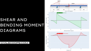
Shear and Bending Moment Diagrams:

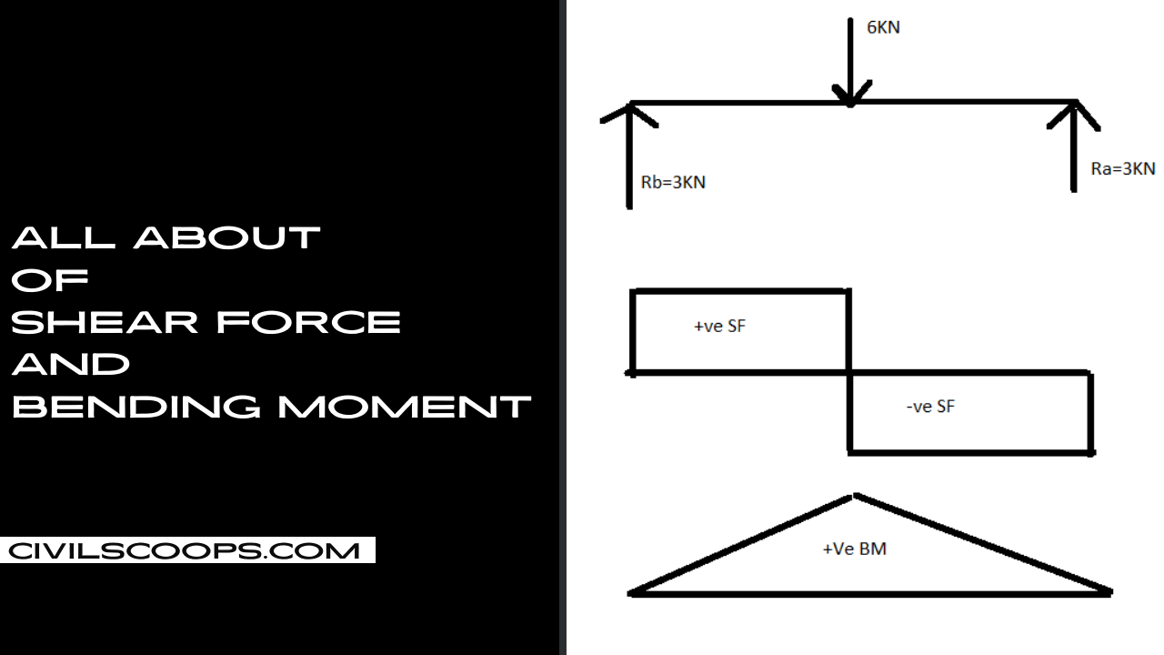
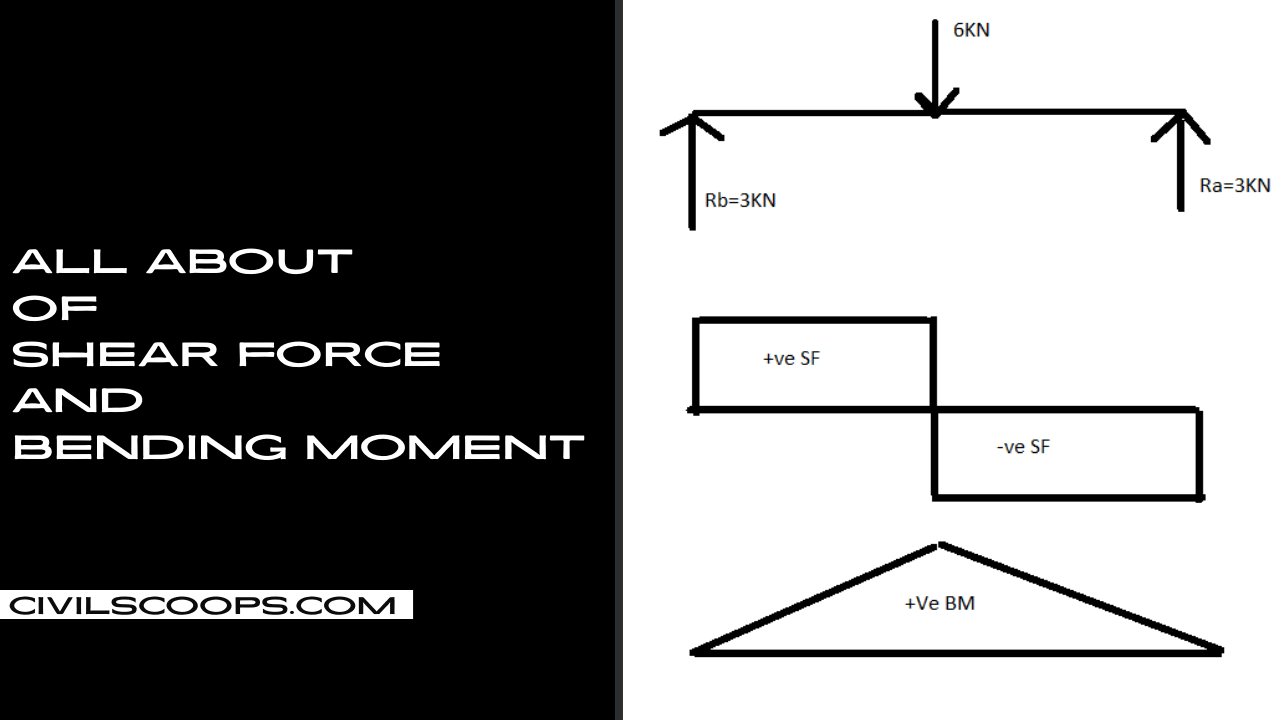
- Most beams are loaded in such a way that the stress produced on planes perpendicular to the beam’s axis consists of a shear force, V, and a bending moment, M.
- It is very useful , if not necessary , to first determine the shear and bending moment diagrams when determining beam responses.
- Calculating the values of V and M at different positions in the beam and plotting the effects is the simple method for calculating the shear and moment diagrams. We will be able to identify vital parts of the beam this way.
- A critical parameter is one in which the highest or critical tension happens.
Section of Maximum Shear
Because the shear, V, at every transverse portion of the beam is the arithmetic average of the transverse force towards the left of the segment, the shear could be measured at a glimpse for most situations.
Also, Read: What Is Road Pattern | Different Types of Road Patterns
Section of Maximum Moment
Whenever the shear force is negative or alters sign, the bending moment will either be a limit or relative maximum, as seen numerically.
Important Points
- Moment will still be positive for beams stretching between two basic pin-jointed supports ( that is no cantilevers ) and will be drawn above the axis even though the beam sags.
- At the point of zero shear stress, the ultimate bending moment happens.
- The reactions at the supports must be assessed before shear force and bending moments can be measured.
- This is normally accomplished by first deciding the reaction at one of the supports ( sum of moments about support = 0 ) and then resolving vertically sum of vertical reactions = 0 ) and determining the reaction at the other support.
Like this post? Share it with your friends!
Suggested Read –
- What is MDF | Advantage s| Disadvantages| Application | Properties | Thickness
- What is Ferro Cement| Properties| Materials required| Uses| Advantages| Disadvantages
- What Is Dampness | Causes of Dampness | Effects of Dampness | Damp Proofing Materials | Methods of Damp Proofing
- What Is ACP | Applications of ACP Sheet | Advantage of ACP Sheet | Disadvantages of ACP Sheet
- What Is AAC Block | When AAC Was First Developed | Advantages of Using AAC Blocks | Disadvantage of AAC Blocks | Properties of AAC Blocks
Frequently Asked Questions (FAQ)
Shear Force and Bending Moment Formula
Many structures can be approximated as a straight beam or as a collection of straight beams. For this reason, the analysis of stresses and deflections in a beam is an important and useful topic.
This section covers shear force and bending moment in beams, shear and moment diagrams, stresses in beams, and a table of common beam deflection formulas.
Shear Moment Diagram Examples
This is a graphical representation of the variation of the shearing force on a portion or the entire length of a beam or frame. As a convention, the shearing force diagram can be drawn above or below the x-centroidal axis of the structure, but it must be indicated if it is a positive or negative shear force.
Shear and Moment Diagram Calculator
Welcome to another Python mini-project. In this project we’re going to build a Shear Force and Bending Moment Diagram calculator using Python in the Jupyter Notebook development environment.
Generating the shear force and bending moment diagram for a simple beam with anything other than basic loading can be a tedious and time-consuming process. Once you finish this project, you’ll have a calculator that can produce shear force and bending moment diagrams at the push of a button.
What Is Shear?
Shear refers to a type of material strain experienced in a structure due to the lateral shifting of its inter-granular plates relative to each other. The degree of tolerable shear stress of a metal is a strong indicator of the metal’s resistance to wear and degradation.
Shear may also refer to a type of force load that is applied to produce material failure along a parallel plane. It is observed as a sliding and twisting wear phenomenon.
What Is Shear Strength?
In engineering, shear strength is the strength of a material or component against the type of yield or structural failure when the material or component fails in shear. A shear load is a force that tends to produce a sliding failure on a material along a plane that is parallel to the direction of the force.
Originally posted 2022-05-27 08:03:12.

