
When it comes to understanding the flow of fluid through a pipeline or channel, measuring discharge is essential. Discharge is the rate at which a fluid, such as water, passes through a certain point. In particular, measuring discharge using an orifice has been a widely used method for many years. This technique involves a circular orifice, or opening, being placed in a pipe or channel to restrict the flow of fluid, allowing for precise measurements. In this article, we will delve into all the aspects of measuring discharge using an orifice, from its working principle to the various applications and limitations. So, let us explore the world of orifice flow measurement and its importance in various industries.
Table of Contents
How to Measure Discharge Using an Orifice?
Measuring discharge, or the amount of fluid flowing through a channel, pipe, or opening, is an important aspect of civil engineering. It is particularly crucial in designing and analyzing hydraulic systems such as water supply networks, drainage systems, and irrigation systems. One common method used for measuring discharge is using an orifice. An orifice is a small hole or opening that is placed in a pipe or channel through which the flow passes.
The basic principle behind measuring discharge using an orifice is to create a pressure difference between the upstream and downstream sides of the opening, which is directly related to the flow rate. The larger the flow rate, the greater the pressure difference. The steps for measuring discharge using an orifice are outlined below.
1. Select an appropriate orifice plate: The first step in measuring discharge using an orifice is to select the right orifice plate. The orifice plate is a thin metal disc with a precisely sized hole in its center. It is inserted into a pipe or channel and is held in place by a flange or other attachment. The plate should be chosen based on the expected range of flow rates and the properties of the fluid, such as its density and viscosity.
2. Install the orifice plate: Once the plate is selected, it should be properly installed in the pipe or channel. The plate should be placed at a right angle to the direction of the flow, and the sides should be parallel to the flow. Any roughness or damage on the edges of the plate should be smoothed to ensure accurate measurements.
3. Measure the pressure difference: After the plate is installed, the next step is to measure the pressure difference between the upstream and downstream sides of the orifice. This is usually done using a differential pressure gauge or a manometer. The pressure difference is directly proportional to the flow rate and can be converted into flow rate values using a flow rate calculator or a flow rate chart specific to the orifice plate used.
4. Consider the discharge coefficient: While measuring the pressure difference, it is essential to take into account the discharge coefficient, which is a measure of how much fluid passes through the orifice in comparison to the theoretical discharge. The discharge coefficient is affected by various factors such as the shape and size of the orifice, the Reynolds number (ratio of inertial forces to viscous forces), and the properties of the fluid.
5. Repeat the process: To ensure accurate and reliable results, the measurement process should be repeated multiple times. Each time, the average of the pressure difference readings should be taken to account for minor variations or errors.
In conclusion, measuring discharge using an orifice is a simple yet effective method in civil engineering. It is essential to follow the correct installation and measurement procedures to obtain accurate results. Additionally, it is crucial to consider factors such as the discharge coefficient to ensure accurate and precise estimations of the flow rate.
Flow Through an Orifice
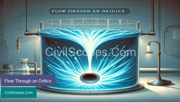
Flow through an orifice is a common term used in civil engineering and fluid mechanics. Simply put, it refers to the movement of a liquid or gas through an opening of a certain shape and size, also known as an orifice. This flow of fluids through an orifice is crucial in many engineering applications and is extensively studied to understand its behavior and characteristics.
An orifice is usually a circular or rectangular opening in a solid surface, such as a pipe, wall, or partition. It can also be a hole in a thin plate or a nozzle. The orifice is designed to restrict the flow of fluids and create a pressure difference between the upstream and downstream sides, causing the fluid to flow from high to low pressure.
The flow through an orifice is governed by various factors such as the orifice diameter, the fluid properties (density, viscosity), the upstream pressure, and the shape of the orifice. The most common type of flow through an orifice is a subsonic flow, where the fluid velocity is less than the speed of sound. In this type of flow, the fluid particles follow a streamlined path through the orifice, and the energy loss is mainly due to frictional effects.
One of the critical parameters that govern the flow through an orifice is the Reynolds number, which is the ratio of inertial forces to viscous forces. When the Reynolds number is less than 2000, the flow is considered laminar, and when it is greater than 4000, the flow is turbulent. In laminar flow, the fluid particles move in parallel layers, while in turbulent flow, the particles mix and swirl, resulting in higher energy losses.
The flow rate through an orifice is directly proportional to the fluid density, orifice area, and the square root of the pressure difference (or the head) across the orifice. It is also inversely proportional to the fluid viscosity. This relationship is described by the well-known Bernoulli’s equation, which states that the total energy of a fluid remains constant throughout the system.
In practical engineering applications, the flow rate through an orifice is often measured by installing a flow meter at the downstream side of the orifice. This meter is calibrated to measure the volumetric flow rate, which is then converted to mass flow rate using the known density of the fluid. This information is crucial in industries such as water supply, oil and gas, and chemical processing, where accurate measurement of flow rate is essential for the system’s efficient functioning.
The design of an orifice is a crucial aspect of fluid flow in engineering. The shape, size, and location of the orifice play a significant role in determining the flow behavior and pressure losses in a system. In industries such as water treatment and irrigation, orifices are used to control the flow rate and pressure, thus ensuring the desired efficiency of the system.
In conclusion, flow through an orifice is a critical phenomenon in civil engineering, which affects the design and performance of various industries. Understanding the principles and factors that govern the flow through an orifice is crucial in designing efficient systems and optimizing fluid behavior.
Classification of Orifice
Classification of Orifice:
Orifice is a disc or plate with a circular opening, used for controlling the flow of fluid in a pipe or channel. It is a common device used in various hydraulic and fluid flow systems. Orifice can be classified based on various parameters such as shape, function, and head loss.
1. Based on Shape:
a. Circular Orifice: It is the most common type of orifice, with a circular orifice plate installed perpendicular to the direction of flow. It is used for flow measurement and control in pipes and channels.
b. Square Orifice: It has a square-shaped opening and is commonly used for flow measurement in irrigation systems.
c. Triangular Orifice: It has a triangular-shaped opening and is used for controlling flow in pipes and channels.
d. Rectangular Orifice: This type of orifice has a rectangular-shaped opening and is used for flow measurement in channels and rivers.
2. Based on Function:
a. Flow Meter Orifice: This type of orifice is used for measuring the flow rate of a fluid in a pipe or channel. It is installed perpendicular to the direction of flow and is commonly used for water flow measurement in domestic and industrial applications.
b. Restriction Orifice: It is used to reduce the flow rate in a pipe or channel by creating a pressure drop. It is commonly used in pipelines to control the flow of fluids.
c. Venturi Orifice: This type of orifice is used for both flow measurement and flow control. It has a converging section, a throat, and a diverging section which creates a pressure difference to measure or control the flow rate.
3. Based on Head Loss:
a. Sharp-Edged Orifice: It has a sharp edge around the opening and creates high head loss in the flow of fluid. It is used for flow measurement in high-velocity flow conditions.
b. Conical Orifice: It has a conical shape around the opening which creates a lower head loss compared to sharp-edged orifice. It is commonly used for flow control in pipelines.
c. Quadrant-Edged Orifice: It has a smooth, rounded edge around the opening and creates the least head loss among all types of orifice. It is commonly used for flow measurement in low-velocity flow conditions.
In addition to these classifications, orifices can also be classified based on the material of construction, such as metal or plastic orifice plates, and based on the method of installation, such as flange-mounted, or threaded orifice plates. The choice of orifice type depends on the specific application and requirements of the system.
In conclusion, the classification of orifice provides a comprehensive understanding of the different types and their applications. It helps in selecting the right type of orifice for a specific system and ensures efficient flow control and measurement. As a civil engineer, it is essential to consider the various factors such as shape, function, and head loss while designing orifice for a particular project.
Conclusion
In conclusion, measuring discharge using an orifice is a widely used and effective method for determining the flow rate of liquids through pipes and channels. By understanding the underlying principles and variables involved in this process, engineers and scientists can accurately measure discharge and make informed decisions for various applications such as irrigation, water supply, and sewage management. With the advancements in technology, there are now sophisticated instruments and devices available for precise and reliable orifice flow measurement. It is essential to continuously monitor and maintain the orifice for accurate results, and regular calibration is crucial for the long-term success of the measurement system. Overall, an orifice is a valuable tool in the field of fluid mechanics and plays a vital role in water resource management and industrial processes.