What Is Bridge Abutment | 5 Types of Abutments
Table of Contents
Bridge Abutment Means
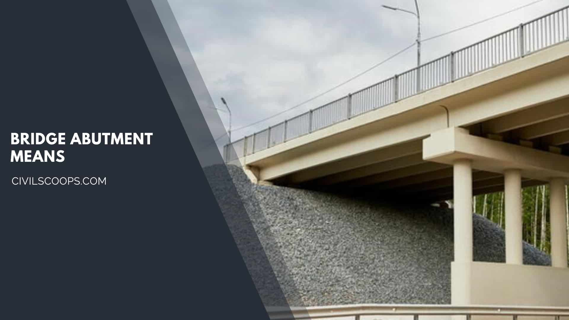
As a component of a bridge, the abutment provides the vertical support to the bridge superstructure at the bridge ends, connects the bridge with the approach roadway, and retains the roadway base materials from the bridge spans.
Although there are numerous types of abutments and the abutments for the important bridges may be extremely complicated, the analysis principles and design methods are very similar.
In this article, the topics related to the design of conventional highway bridge abutments are discussed and a design example is illustrated.
Unlike the bridge abutment, the earth-retaining structures are mainly designed for sustaining lateral earth pressures.
What Is Bridge Abutment?
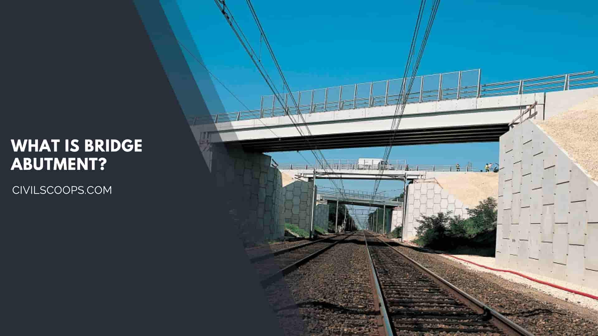
A bridge abutment is a substructure that supports one terminus of the superstructure of a bridge and, at the same time, laterally supports the embankment which serves as an approach to the bridge.
For a river bridge, the abutment also protects the embankment from scour of the stream.
Bridge abutments can be made of masonry plain concrete or reinforced concrete.
Also Read: What Is Bridge Pier | Type of Bridge Pier
Useful Article for You
- What Is a Highway Flyover
- What Is Grouting
- What Is a Pile Cap
- What Is a Bond Beam in Masonry
- What Is Sapwood
- What Is Crane
- What Is a Gable
- What Is Superelevation
- What Is Kerb
- What Is the Purpose of Washers
- What Is the Size of a Brick in Inches
- What Is Reinforced Masonry
- What Is Workability
- What Is Bond Breaker
- What Is Plasticizer in Concrete
- What Is Luminous Flux Vs Lumens
- What Is Caisson
- What Is an Undercoat
- What Is a Benchmark Surveying
- What Is Bracing in Construction
- What Is a Beam in Construction
- What Is the Standard Door Frame Size
- What Is a Spandrel Beam
- What Is a Fire Escape
- What Is a Weep Hole
- What Is Tie Beam
- What Is Fine Aggregate
- What Is Pony Wall
- What Is Flag Stone
- What Is Development Length
- What Is Cement Plaster
- What Is a Pitched Roof
- What Is Rafters
- What Is a Slab in Construction
- What Is a Monolithic Slab
- What Is Linear Distance
- What Is Shovel
- What Is Lintel in Construction
- What Is a Concept Sketch
- What Is Mezzanine Floor
- What Is Man Sand
- What Is Plaster Made Out of
- What Is a Floating Slab
- What Is Falsework
- What Is Bituminous
- What Is a Spillway
- What Is Curb and Gutter
- What Is Dampness
- What Is Lap Length
- What Is the Full Form of Fsi
- What Is Door Frame
- What Is Plinth Protection
- What Is Traffic Rotary
- What Is Grade Slab
- What Is Inverted Beam
- What Is Rolling Margin of Steel
- What Is Modulus of Rupture
- What Is Fresh Concrete
- What Is Dpc in Construction
- What Is Earthen Dam
- What Is Short Column
- What Is Sbc of Soil
- What Is Plum Concrete
- What Is Flyover Bridge
- What Is Isolated Footing
5 Types of Abutments
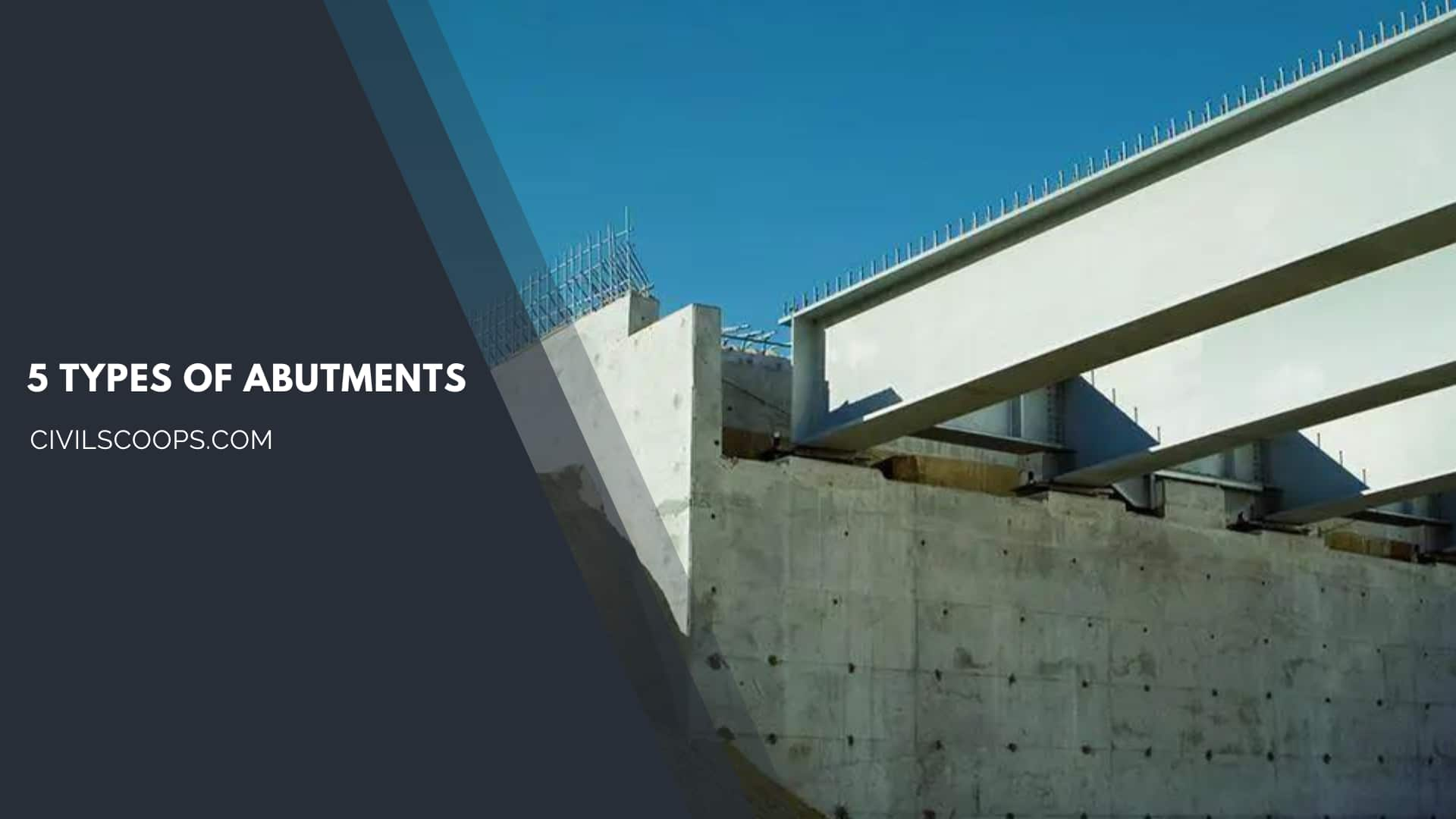
The types of Abutments are as follows.
- Closed Abutment.
- Stub or Perched Abutment.
- Pedestal or Spill-through Abutment.
- Integral End Bents.
- Mechanically Stabilized Abutment
1. Closed Abutment
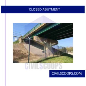
Typical full height closed abutment
A closed abutment is a full-height wall with wing walls on each side that retains the full height of the approach embankment. This type of abutment minimizes the required span length of the bridge. However, there are several significant disadvantages, especially for high embankments and embankments on soft foundations.
The abutment must be constructed before the adjacent embankment. Proper placement and compaction of backfill are difficult in the restricted area between the and the wing walls. If heavy equipment is used to compact the backfill, the wall may be pushed laterally and out of vertical alignment.
The weight of the backfill will contribute to the compression of soft foundation soils and the post-construction settlement of the embankment and abutment.
If the abutment is supported on piles, the compression of the foundation soil will produce down drag, which may overstress the piles.
Closed abutments must be designed for the lateral earth pressures exerted by the full height of the approach embankment. Rankine earth pressure theory or equivalent fluid pressures conventionally are used.
Because the lateral force and the overturning moment about the base of the wall are proportional to the square and the cube of the wall height, respectively, the structural requirements and cost of the wall increase rapidly with height.
Also Read: Repairing Water Damaged Wall | How to Repairing Water Damaged Wall | How to Fix Water Damaged Wall
2. Stub or Perched Abutment

A stub or perched abutment is a relatively short abutment that is constructed after the embankment has been completed. The embankment can be compacted without interference from the abutment, and, if necessary, the abutment construction can be delayed until the compression of the foundation soils caused by embankment loads is completed.
Thus, post-construction settlements may be minimized. The abutment may be supported on spread footings in the embankment or on piles or drilled shafts constructed through the fill, as shown in the above figure.
Because the stub abutment is relatively short and located in the upper part of the fill, the lateral earth pressure is relatively small in comparison to the pressure against a full-height closed abutment.
However, longer bridge spans may be required than for a full-height abutment. Stub abutments also are used on the natural ground in cut slopes. Spread footing, pile, or drilled shaft foundations may be used.
3. Pedestal or Spill-through Abutment
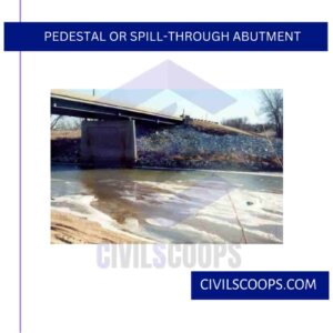
Typical Spill-through Abutment
Pedestal or spill-through abutments are short stub-type abutments supported on pedestals or columns extending to the natural ground. As with closed abutments, the abutment must be constructed before the approach embankment.
Then the fill is placed simultaneously on both sides of the pedestals to minimize the unbalanced earth pressure and the lateral movement of the abutment.
However, the fill around the pedestals is very difficult to compact properly. It also is very susceptible to erosion unless the end slope is protected with paving, riprap, etc.
The lateral earth pressures against a spill-through are less than for a full-height closed abutment but greater than for a stub abutment. The weight of the fill that is placed after the construction of the abutment may cause compression of soft foundation soils and the same detrimental post-construction effects that have been described for closed abutments.
Useful Article for You
- How Wide Is a Cinder Block
- How Much Is a Coffered Ceiling
- How to Make Mortar
- How Long Does Hempcrete Last
- How to Use a Hand Sight Level
- How to Construction
- How to Build a Lean to Roof
- How Are Tunnels Built
- How to Layout a Building
- How Wide Is a Car Parking Space
- How Do Shear Walls Work
- How to Measure Concrete Slump
- How Are Bridge Foundations Built
- How to Use Washers with Screws
- How Dense Is Sand
- How High Is a Window from the Floor
- How to Fix Spalling Concrete Foundation
- How Does a Beam Bridge Work
- How Do They Pour Concrete Under Water
- How Does a Sewer System Work
- How High Are Countertops
- How to Seal Brick Wall Interior
- How to Resurface Cement
- How to Use Portland Cement
- How Is Plaster Made
- How to Find Fineness Modulus
- How to Get Rid of Spray Paint Smell on Metal
- How Many Types of Slope Are There
- How Big Is a Stair Landing
- How Does Rebar Help Concrete
- How to Identify a Load Bearing Wall
- How to Get Paint Off Concrete Without Chemicals
- How to Fix Water Damaged Drywall
- How Much to Get Septic Pumped
- How to Cut a Nail or Screw
- How Long Does Wet Concrete Take to Dry
- How Is Varnish Made
- How Does Ejector Pump Work
- How Does Hydrometer Work
- How to Get Wet Blood Out of Carpet
- How to Build House on Slope
- How Thick Is Plaster Wall
- How Suspension Bridges Work
- How to Seal a Concrete Roof
- How Was Cement Invented
- How to Calculate Area of Steel
- How to Check Silt Content in Sand
- How a Building Is Constructed
- How Are Roads Classified in India
- How Many Types of Cement in India
- How to Find Contour Interval
- How to Stop Leakage from Ceiling
- How Hardness of Brick Is Tested
- How Many Types of Paint Brushes Are There
- How to Calculate Skirting Area
- How Many Types of Beam
- How to Make Road
- How Many Types of Chain in Surveying
- How to Calculate Weight of Steel Bar
- How to Find One Way and Two Way Slab
- How to Calculate Shear Force and Bending Moment
- How Many Type of Houses
4. Integral End Bents

Typical Integral Abutment.
Integral end bents are stub abutments that are rigidly connected to the superstructure without expansion joints. The connection is designed for full transfer of thermal stresses from the bridge deck to the abutment.
The elimination of expansion joints with movable bearing systems for the deck is reported to reduce construction and maintenance costs.
Various designs are used by different state agencies, but almost all require steel H-piles for support of integral abutments. A typical integral end bent is shown in the above figure.
Integral abutments have been used in the United States for about 30 years. Early applications in Kansas, Missouri, Ohio, and Tennessee were restricted to relatively short bridges, generally less than 100 ft (30 m) long.
Today integral abutments are used in more than half of the states, and the allowable lengths have increased significantly. Greimann et al cite the successful use of integral abutments for continuous-steel and concrete bridges with lengths of 300 ft (90 m) and 500 to 600 ft (150 to 180 m), respectively.
Almost all states that use integral abutments on piles indicate that they are performing well. Despite the apparent increasing popularity of integral abutments, some problems have been noted. These problems generally are related to cyclic lateral movements of the abutment in response to thermal stresses in the bridge deck.
Cracking and buckling of approach pavements have been reported. The approach pavement design must include careful consideration of the thermal effects from integral abutments.
Because most backfill materials are not perfectly elastic, cyclic abutment movements create voids between the backfill and the abutment, which permit erosion of the backfill and progressive deterioration and settlement of the backfill.
Groundwater or surface water that enters the backfill through pavement cracks accelerates the erosion process.
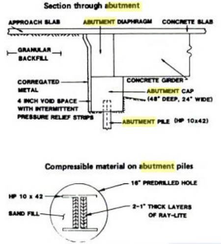
Special Integral Abutment Design
Some states use special details to accommodate the cyclic abutment movements. For example, one North Dakota design, which is illustrated in the above figure, provided a pressure relief system between the backfill and the but merit.
Narrow vertical strips of 4 in (100 mm) thick compressible material were attached at 4 ft (1.2 m) intervals along with the hack of the abutment.
Corrugated metal sheets were placed behind the compressible strips to maintain a 4 in (100 mm) void between the abutment and the backfill.
Also, to facilitate lateral movement of the H-piles, 2 in (50 mm) thick compressible material was glued to both sides of the upper 20 ft (6 m) of the web.
An oversize hole was drilled to a depth of 20 ft (6 m), and the pile was placed in this hole and driven to a depth of approximately 110 ft (33 m).
The oversize hole was backfilled with sand. The performance of this system is reported by Jorgenson. The performance of integral abutments could be improved by the development of new compressible elastic materials that could be installed easily between the abutment and the backfill.
The ideal material would have elastic properties that permit large recoverable cyclic movements and hydraulic properties that provide adequate drainage without erosion of lines from the backfill.
Also, almost all agencies require steel H-piles for support of integral abutments, on the assumption that this facilitates lateral movement.
Currently, there is no evidence to support this hypothesis. Significant savings could be realized if it were demonstrated that integral abutments on spread footings will perform as well as those supported on piles.
5. Mechanically Stabilized Abutment
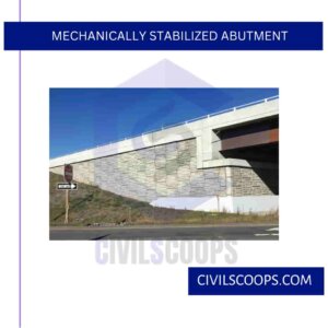
Schematic Diagram of Mechanically Stabilized Abutment
Mechanically stabilized walls, also have been used to support bridge abutments. The bridge seat and footing are supported directly on the reinforced backfill, as shown schematically in the above figure.
The design concepts for the mechanically stabilized walls are applicable. The abutment loads increase the reinforcement requirements, especially in the upper part of the backfill, where the bridge loads are concentrated.
However, the facing elements are not affected because the facing does not support structural loads. There are many proprietary systems that are based on different design assumptions, but generic design procedures are recommended by Mitchell and Vinci and Christopher et al.
Because mechanically stabilized abutments can tolerate large deformations, they often are an economical alternative to deep foundations or treatment of soft foundation soils.

For example. in 1972 mechanically stabilized abutments were used for a bridge across the Moselle River at Thionville, France because large approach fills settlements were anticipated.
The abutment was surcharged until 12 in (0.3 m) of settlement occurred and then the superstructure was constructed. Six months after completion of the superstructure, the bridge seat was jacked 2.4 in (60 mm) to compensate for additional settlement.
Since the bridge was opened to traffic, less than 0.5 in. (12 mm) of settlement has been observed. Because the abutment and approach fill settle as one unit, a differential settlement between the bridge deck and the approach roadway is virtually eliminated.
The speed and case of construction have contributed to the wide-spread use of mechanically stabilized abutments in the United States.

They are especially useful for new and rehabilitation projects in urban areas where right-of-way and work areas often are restricted. For example, they have been used extensively in the Atlanta area. Also, tied-back abutments have been used for widening and rehabilitation projects in cuts.
[su_box title=”FAQ” style=”default” box_color=”#333333″ title_color=”#FFFFFF” radius=”3″ class=”” id=””]
What Is Bridge Abutment?
A bridge abutment is a structure which connects the deck of a bridge to the ground, at the ends of a bridge span, helping support its weight both horizontally and vertically.
What Is Abutment in Bridge?
Abutments are usually constructed of concrete. The abutment seat is the most vulnerable part of the abutment, especially on bridges with leaking expansion joints.
Concrete Abutment
Abutments are used at the ends of bridges to retain the embankment and to carry the vertical and horizontal loads from the superstructure to the foundation.
Types of Abutments
There are four types of bridge abutments: typical gravity, U-abutment, spill-through, and pile bent. There are other types too, such as full-height abutments, semi-stub abutments, stub abutments, integral abutments, and semi-integral abutments.
Wing Wall in Bridge
In a bridge, the wing walls are adjacent to the abutments and act as retaining walls. They are generally constructed of the same material as those of abutments. The wing walls can either be attached to the abutment or be independent of it.
Bridge Abutment Types
- Gravity abutment, resists horizontal earth pressure with its own dead weight.
- U abutment, U-shaped gravity abutment.
- Cantilever abutment, cantilever retaining wall designed for large vertical loads.
How Are Bridge Supports Built in Water?
A pile of appropriate size is set onto the subsurface of the body water and then hammered down by the pile driver. The piles are battered either outward or inward at an angle, thus allowing them to support the lateral load of the upper bridge structure while also being able to withstand the currents of the water.
Types of Abutments in Bridges
[/su_box]
[su_note note_color=”#F2F2F2 ” text_color=”#333333″ radius=”3″ class=”” id=””]
Like this post? Share it with your friends!
Suggested Read –
- What Is Pointing
- Corian Countertops
- What Is Scrap Value and Salvage Value
- Introduction of Gantry Girder | Load on Gantry Girder
- Difference Between Flexible Pavement and Rigid Pavement
[/su_note]
Originally posted 2023-10-28 11:38:38.
